Click on the Registration link above for a Free Account so you can access training and videos as I add them as we go along.
In Part 1 (Click Here to read part Part 1), we laid out some basic concepts and background for transformer vector groups. We did some calculations to prove how the voltage (and current – assuming unity power factor for a load) shifts from Primary to Secondary terminals of the transformer depending how the windings are wired internally and how the lead terminals are brought out.
We now continue to further explain and illustrate this concepts. After-all, this subject is very important and deserves it’s own attention.
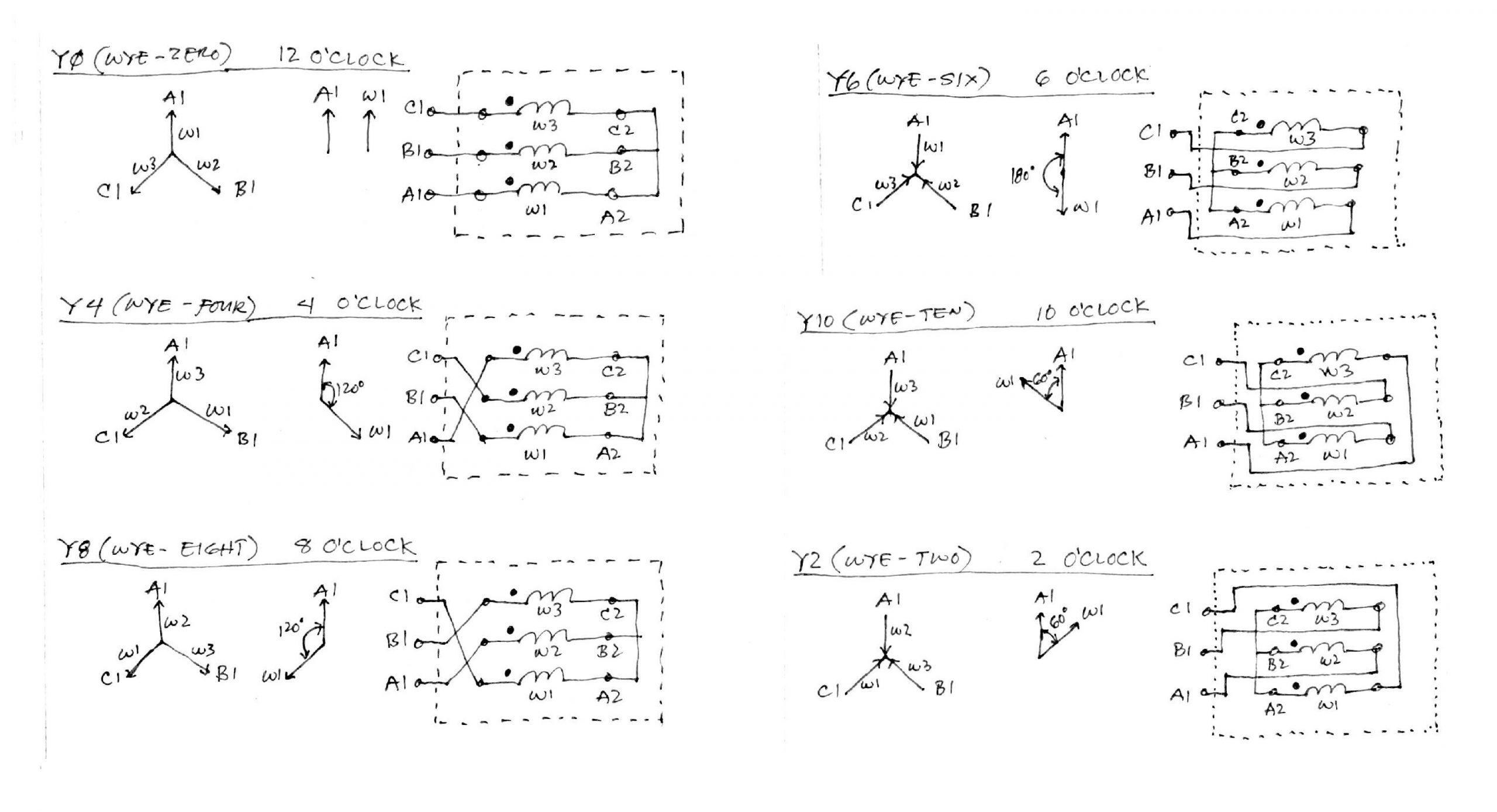
Six (6) Ways to Wire Star (or Wye) Winding
Examine below Figure-1 and note how the windings (W1, W2, W3), the internal leads (A2, B2, C2) and the external leads (A1, B1, C1) are connected.
The dotted lines enclosing the windings and internal leads marks the demarcation between internal and external parts of the transformer.

As you can see above, by varying how the three internal windings are connected and how the leads are brought outside, we were able to achieve different voltage phase shifts between terminals (A1, B1, C1) with respect to internal/phase winding (W1, W2, W3) for the star connection.
In summary, we have the following voltage shifts for star winding – 12 O,Clock (zero degree), 4 O,Clock (+120 degree), 8 O,Clock (-120 degree), 6 O,Clock (180 degree), 10 O,Clock (-60 degree), 2 O,Clock (+60 degree).
Six (6) Ways to Wire Delta Winding
Figure-2 below, shows six ways we can connect delta winding of a transformer.

Similar with the star connection, we can also achieve varying voltage shifts between terminals (A1, B1, C1) and the internal phase voltage (W1, W2, W3).
In summary, we have the following voltage shifts for delta winding – 1 O,Clock (+30 degree), 5 O,Clock (+150 degree), 9 O,Clock (-90 degree), 11 O,Clock (-30 degree), 3 O,Clock (+90 degree), 7 O,Clock (-150 degree).
Phase Shifts Between Primary and Secondary Voltage in a Transformer
Now that we have clearer picture of each delta and wye configurations, let us try to combine to come up with the whole picture of a complete transformer arrangements.
In Part 1 post, we investigated a Dy11 connection. Let us use that same example again for easy flow of the discussion.
The questions now comes to mind – How do I mix and match these delta and wye connections? Which ones out of the six star connections and six delta connections should I combine to come up with a Dy11 transformer?
In Figure-3 below, I’ve worked out 3 examples for Dy11, Dy1 and Dd6.

Using phasor diagrams it is much easier to visualize and prove that in order to achieve a Dy11 we need a D11 for the HV side and a Y0 for the LV side.
In Figure-3 above, let’s establish some procedure and analyze how to rationalize the phasor relationships between HV and LV sides. We already proven in Part 1 by using manual calculations that the connections above for Dy11 is correct.
Now, I’d like to think along these way-
- I know that for a Dy11, I need a Delta on HV and a Wye on LV side.
- I know that the HV side will become the Hour Hand of the clock and the LV will become the Minute Hand of the clock – read back on Part 1 if you miss this part.
- I know that the phasor rotation is counter-clockwise, therefore I also know that at 11 O’Clock the HV (Hour Hand) will lead the LV (Minute Hand) by 30 degrees. Clear so far?
- For a Y0 connection I can see that W1 is in phase with A1. On the other hand for a D11 connection, I can see that A1 leads W1 by 30 degrees based on a counter-clockwise rotation.
- I know that winding voltages between Primary and Secondary windings are always in-phase with each other. Therefore, I know that W1/Secondary will be in-phase with W1/Primary ALWAYS. This also means that A1/Secondary will be in-phase with W1/Primary. Still clear?
- Now, I can supper-impose Y0 phasor on top of D11 phasor and then rotate the whole thing counter-clockwise such that A1/Sec (Minute Hand) is at 12 Hour Position. This will also rotate along the A1/Pri (Hour Hand) to the 11 Hour Position thereby forming 11 O’Clock.
For your assignment! – Try to do the phasor shifts for Dy1 and Dd6 as shown above. Also have a look at Part 1 for some more vector connections and work out how they can be achieved.
Please share if this has been helpful!

