
A Case of an Actual Project
Below is a portion of a 12.5kV medium voltage switchgear single line diagram I reviewed few weeks ago. There are more information in the actual drawing but for the purpose of this discussion, we will just look at one item – the station service transformer as shown below.
Station service transformers, as the name suggests, are transformers that are used to provide local power to the substations. These transformers are normally small and can be three phase or single phase. They are usually connected to the switchgear bus on the primary side and on the secondary side connected to an AC distribution panelboard.
The AC distribution board are then used to supply power for relays and other instruments and to provide control circuit power, as well as charge the station batteries.
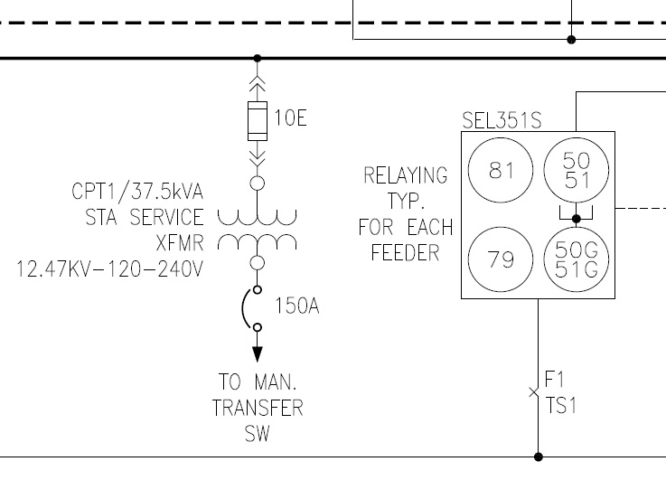
Figure-1: Protection & Control Single Line Diagram
Checking Process
In order to check whether the protection settings selected by the vendor complies with the standards, we need references such as – the National Electrical Code and the vendor supporting documents such as data sheets. However, in some cases, the data sheets are not available especially during the very early stages of the design, such is the case in this situation.
Referring to NEC Table 450.3 (A), we can determine the recommended rating or setting the Overcurrent Protective Device (OCPD) that should be selected for both primary and secondary of the transformer.
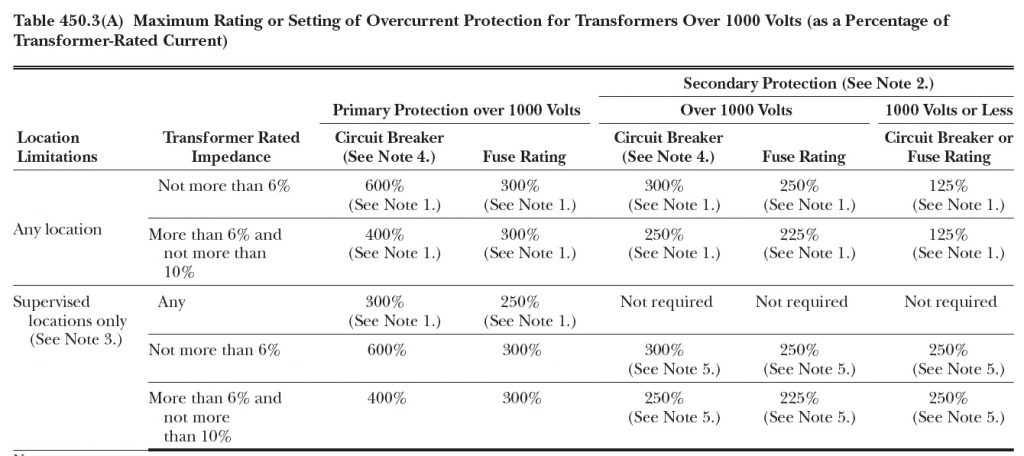
Figure-2: Table 450.3(A) Maximum Rating or Setting of Overcurrent Protection for Transformers Over 1000 Volts (as a Percentage of Transformer-Rated Current)
Primary Protection
Using the table we are able to know that the primary protection must be 300% of primary rated-current if a fuse is specified.
Calculating for primary rated-current, yields:
Ip = 37,500/12,470 =3Amps
Calculating for maximum fuse rating for the primary protection, yields:
Primary protection rating (fuse) = 300% x 3A = 9Amps
However, the 9 ampere calculated value is not a standard fuse rating. The next commercially available E-rated fuse is rated at 10A. Therefore, the vendor has specified the right rating in this case.
Secondary Protection
Using the table again, the secondary protection must be 125% of the secondary rated-current if a circuit breaker is specified.
Calculating for secondary rated-current, yields:
Is =37,500/240 = 156.25Amps
Calculating for maximum circuit breaker rating for the secondary protection, yields:
Secondary protection rating (circuit breaker) = 125% x 156.25A = 195.31Amps
Referring to NEC Table 240.6(A), we will be able to determine the next standard circuit breaker rating available. In this case, is a 200A breaker.

Figure-3: NEC Table 240.6 (A) Standard Ampere Ratings for Fuses and Inverse Time Circuit Breakers
Conclusion
I made a recommendation to the designer to change the setting that they specified as 150A and instead use 200A.
I hope this has been a good and short refresher for you. Please do me a favor and share with our electrical practitioner friends.